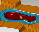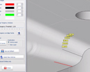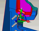
WorkXplore 3D - Dynamic Sectioning
The Dynamic Section function allows you to explore inside a part or an assembly according to a plane or a guide curve (lines, circles, Bsplines, polylines and composites), which can be moved during analysis. You can also take measurements on the created sections.The cross section be extracted as geometric entities.
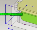
WorkXplore 3D - Bounding Box
Instantaneous generation of the bounding box (Rectangle, Cylindrical..) of a part or a set of parts which provides information on the dimensions, volume, weight of the selected elements. Can also be used to determine the optimal stock model required for manufacturing.
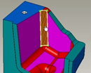
WorkXplore 3D - Face and object information
Precise measurement information: Information is available both on objects and surfaces and enables rapid calculation of volumes and areas. Complementary information such as the object name, encumbrance, number of faces, etc. is also available.
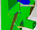
WorkXplore 3D - Draft Angles
The calculation and display of drafts and undercuts are extremely quick, even on very big parts. WorkXplore 3D automatically colors drafts and undercuts according to the mold stripping axis. Precise draft angle values are displayed dynamically as the mouse is dragged over the surfaces and can be inserted by default in the 3D model.
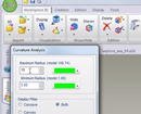
WorkXplore 3D - Curvature Analysis
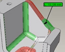
Curvature radius and plane face analysis is a valuable tool for users enabling fast cost and production time evaluation. The coloring of elements to be analyzed is automatic and users can insert measurement labels containing precise values of the elements selected. With WorkXplore 3D, the user can view only the concave radii, the convex radii, or both
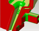
WorkXplore 3D - Plane faces and Face types Analysis
During the part analysis, you can show all surfaces that are planar, perpendicular or non planar. You can also differentiate face types (planes, cylinders, cones...), group together the different faces of the model and attribute a different color to each type.
WorkXplore 3D - Automatic 3D Model Comparison
The Automatic comparison of 3D models function features a 3D graphic display of the difference between two versions of the same model. The modifications are clearly identifiable by color to distinguish material added from material removed. By clicking on the model, the user can measure the difference in material between the two models


